In August 2019, I found myself answering a lot of questions about TTL timing, breadboarding etc. because a lot of people have been building Ben Eater CPUs and he has built a simple video display that shows a static low resolution image. His runs with a 10MHz clock which is about the upper limit for simple TTL circuits on breadboard. So I designed a fully synchronous design that works at the full 25MHz VGA clock speed, which I figure is an inevitable request from the community and I know from experience that it is tricky to get right.
This could have just been all done inside an FPGA, but the aim of this project is to make a board which can be hand-built and serves as a learning experience, so this is an important requirement. It also has to be possible to make it on breadboard, so surface mount devices have to be ruled out. In practice I used the modern equivalent of TTL which is 74HC parts and some 74AC which are faster. Of course the frame store is made from static RAM chips.
I chose to use a serial connection beause a) old terminals had them, and b) they are easy to use with microcontrollers and readily understood by everyone.
Because of this I need a UART receiver, but to do that in TTL would be a whole other chapter for the project; instead I have used a PIC CPU, which means I can support a PS2 keyboard for a 2-way experience. Purists may argue that it is no longer a TTL terminal, however it still works without the PIC so if you prefer you can leave it out and make your own arrangements for putting characters in the frame store, loading the font RAM and making a UART.
I chose this because it is the most common standard that everyone is likely to have a monitor for, LCD or CRT types. It requires a 25.175MHz pixel clock which is challenging for a breadboard build.
To support graphics you need have a very fast host interface, which RS232 is not. Also, to draw the ASCII characters would require rendering the fonts in software, which is a CPU-intensive process. Really you need at least an ARM CPU to get decent performance, which is not likely to be available in a DIP package so proper graphics is outside the scope of the project.
To mitigate the lack of graphics, the character set includes many box-drawing characters and 64 user-defined characters and, since V1.2 of the firmware, supports pseudo-graphics (see the software page for more details).
The character set I chose was 8x14 pixels and I left the first 2 lines blank giving an 8x16 character. Divide this into 640x480 and you get 80x30 characters. This is a common (old) standard and is enough for most purposes. I chose to support 16 colours - all VGA monitors are colour and to support 256 colours or more is really a graphics requirement.
Traditionally the fonts are stored in a ROM and I could use an EEPROM or Flash device but they tend to be slower than RAM and you have to program them so I chose to use another SRAM of the same type as the character store. The fonts are loaded by the PIC on power up. Cursors could be generated by hardware, but for simplicity we've chosen to do it in software.
To make it compatible with existing software that might use a terminal e.g. Linux, the most common ANSI escape sequences are supported. The software page contains the full list of supported commands.
All the design information is available on this site and is free for personal use. The schematics and build information plus the PIC software can be found on the resources page. The Technical Details page gives a detailed description of how the circuit works.
If you're interested in making a PCB version, please contact us.
Click any of the images here to open them full-size in a new tab.

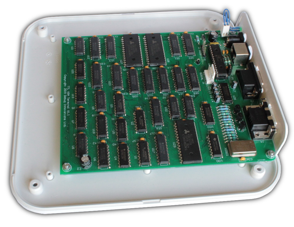
This is a fully assembled V1.1 PCB.

It's entirely possible to build the TTL terminal on breadboard (this is a photo of the prototype).
Note that the design in this photo is not exactly the same as in the schematics. Do not try to copy the exact wiring in this photo. Use the schematics provided.
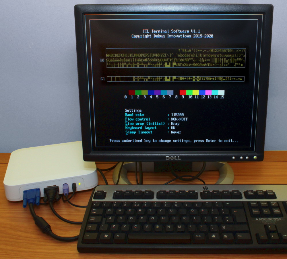
This is an example of a boxed TTL terminal with a monitor and keyboard, showing the settings screen.
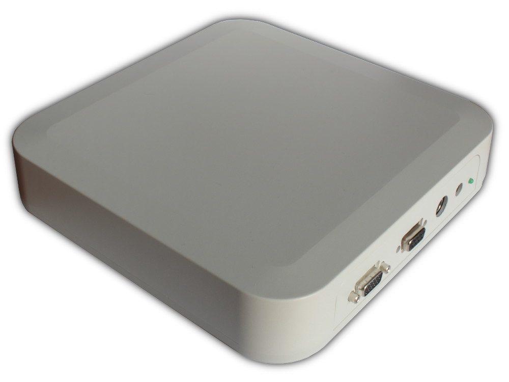
The board can be put in a box if required.